
Author: Ralf Banning, May and June 2020, with updates in June and September 2021
Version: 2021-06-18
Since decades a suitable manufacturing model for industries has been discussed in the scientific community (see literature list) and was described in various international standards like STEP and PSL. Despite these efforts, no general or generally agreed meta-data model for manufacturing can be found in practice to day. Even looking deeply in to widespread IT-systems like SAP ERP or SAP ME, an archeology-like stratification of terms and definitions will emerge. It seems as if it has to be accepted, that in real-life we have to work with a broad variety of terms and data models. So, for example, the part of the engineers, might be the material of the production planners, and the same object will be sold as product by the sales department finally. This also shows that giving objects a name - the ontology of objects - depends on the context of their usage.
An other major issue shows up when we consider non-tightly-integrated information systems like in the flecsimo case, where many of the communication have to be promoted via network and "flat-structured" messaging protocols. As it shows up, the classical ERP-like data model with separated data entities for demand planning (i. e. BOM) and production planning (i. e. routing) does not really fit: the routing lacks task related information on material in- and output, the BOM does not reflect the time and resource structure. By a remark in Kurbel (2013, p. 65), Helmut Kernler proposed a so called "Resource List" structure to overcome similar problems (see Kernler, 1995), which is also used in today's SAP Supply Chain Management (SCM) systems and is known as "Production Data Structure" (PDS). Therefore, in our manufacturing data model we will use a master data structure which implements Kernlers Resource List in a similar way SAP did it with SAP SCM (for more details see elsewere TBD).
Keeping this in mind, the flecsimo manufacturing data model is designed to meet the following objectives:
- use manufacturing related (domain-specific) terms for system objects
- use short and simple names for attributes
- provide a transparent transformation of terms from business domain to the domain of manufacturing
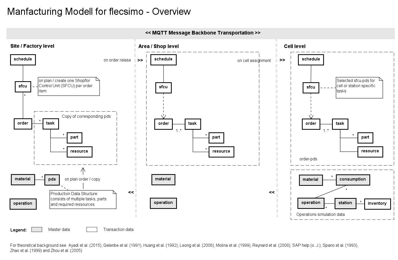
The second objective is also driven by the fact, that the different layers of the flecsimo model (site, area and cell) are only interconnected by the light-weight messaging protocol MQTT, and therefore the JSON-format payload of MQTT messages will be more "readable" for humans by using clear and short attribute names. The "layers" mentioned before, are related to models as discussed e. g. by Molina and Bell (1999), dating back to the ESPRIT Project 932 factory model. Based on the first three levels (Factory = site, Shop = area and Cell = cell) the basic data structure for flecsimo is defined as follows (click on diagram will enlarge):
")
The flecsimo site-area-cell-model maps to this structure in following simple way:
- site → Factory
- area → Shop (Area)
- cell → Cell
- station → Station
Data Processing
The basic idea of processing the data is:
- Orders for manufacturing will be received from an external system (like customer orders, or interface to an SAP ERP system providing IDocs).
- When such an order is received, the relevant data will be stored in the order entity. To be able to process the order, the order data have to match the stored master data (pds and material) at the factory (site) level.
- After quality check of data and planning an optimization (not shown in the model so far!) the order will be released to the shop (one or more areas).
- With this release, the order is split into shop floor control units (sfcu, one per item) and the data is transferred to the assigned area(s). In most cases a typical flecsimo setup will only comprise one area!
Having assigned the responsible manufacturing area, the next level processing follows these steps:
- The area requests to take over the tasks for an sfcu by an
rfqmessage. - Every cell in this area which is ready (or able) to take over the task, will respond to this request sending a
offermessage. - The area (or a responsible) will select appropriate cells and assign the task by sending a
asgmtmessage to the respective cell.
Data Model
The entities marked in 'grey' background color will hold master or template data, whereas the others are considered to store transaction data. Master data and templates serve as "copy template" data when rolling out production plans or task requests . All instantiation data (a.k.a. as transaction data) will be stored at the level where it is instantiated and published to lower levels afterwards ("downstream"). This "duplication" of data is motivated by the fact, that flecsimo operates as an didactic system which makes every step in data communication transparent and persistent. This will allow detailed analysis on every level.
Multi site operation - impact on data model
(New in revision 25th of June 2020)
The proposal for flecsimo implies that it should be possible to run areas and cells within different sites or areas. Since every component runs it's own persistent operational database and every object id (like order numbers and sfcu id's) is only unique at the site from which the data originates, primary key conflicts may occur, if a component is used within a different site. This is illustrated by the following diagram (click on, to switch page one and two):
Following Design Decision DD_17 including "namespace" or "origin" of transactional data object in the primary key of this objects will provide a solution. It seems to be natural in the context of manufacturing to choose the "site" as this namespace identifier, i.e. every table which may be used in a different context have to implement this "site"-column.
Use Cases
MANDT (as German "Mandant") separates data from different clients. Whereas this client separation approach aims to allow normal users only to see data of one client at a time, the site Primary Key works as a namespace, which generally implies to deal with data of different sites at a time. As a Use Case consider an area of cells which offers operations to varying sites.Implementation status
Multi site operation is supported since commit 588a5603 of gitlab master branch (label 0.1.3), 18th of August, 2020
Site Level Data
(as for version 0.1.3 and higher, documentation of June 2021)
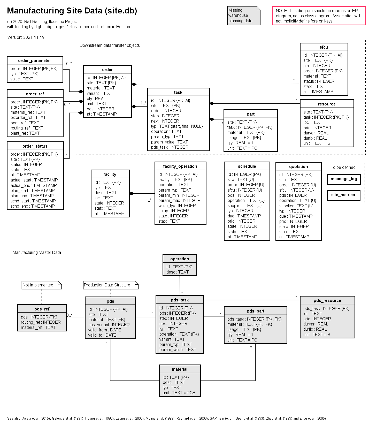
- The pds entity is the header of the Product Data Structure and contains the relation to the master data of material to be produced,
- The pds_task entity contains a link to the operation which has to be performed (e. g. drilling, coating) and a parametrization (e.g. color, drilling diameter).
- The pds_part declares details of consumed and produced materials and its usage ("in", "out") for each task.
- The pds_resource will provide information on required resources (like specific machines) and estimated production times. This may be used as well for planning as for routing within flecsimo.
- The operation entity (on site level) is a simple repository of all serviced operations throughout this site.
- And finally, the material provides a reduced list of materials known for manufacturing (on this site).
As part of the order break down from site-level to cell-level, the order-sfcu-task-part-resource structure is used to message the required information to dedicated areas (and subsequently: cells).
Part instance identity Management
(New in revision 19.11.2021)
Since the sfcu structure will be created as part of order planning, the operational execution of this sfcu's with real, physical parts will start with some delay. Therefore at creation time we have no information which part instance will be taken from stock to fulfill the sfcu's operations. The term part instance refers to every type of materials and parts that will be used to feed the manufacturing process of the stations or will be a matter of transport between them. The identification of an part instance may be provided by the part itself, but in most cases it will an identifier, placed on a transportation container, like a pallet or a box where the part is situated on or in.
In the physical flecsimo models, these parts or containers are represented by small wooden disks with an attached QR-code, which carries a site-unique identification number for this part instance. It is this number, which will be scanned at every station or transportation facility by their built in camera, whenever a part is loaded or unloaded. From this, it is required to associate the part instance identification with the sfcu the first time when this part is withdrawn from stock.
Therefore the sfcu table has to be extended by an additional field, which will named pini (part instance id).
Implementation status
This feature is planned for release 0.2.1 in December 2021
Area Level Data
(as for version 0.1.3 and higher, documentation of June 2021)
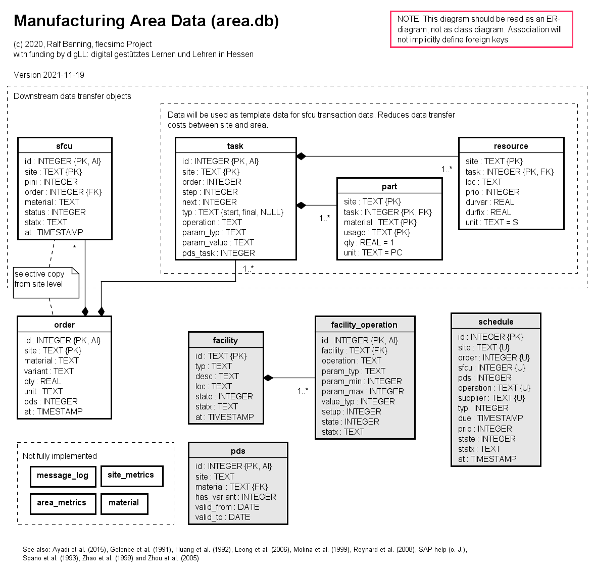
Currently, the area data model contains mainly interfacing data and control data for the processing of task allocation (to cells).
- The entities sfcu, order, task, part and resource are instance copies of the site level and therefore have the same specification.
- During cell allocation (
asgmt) the task-part-resource structure is 'sliced' by using the sfcu-order relation and the facility_operation table to provide the task data only to those cells which can operate them.
Cell and Station Level Data
(as for version 0.1.3 and higher, documentation of June 2021)
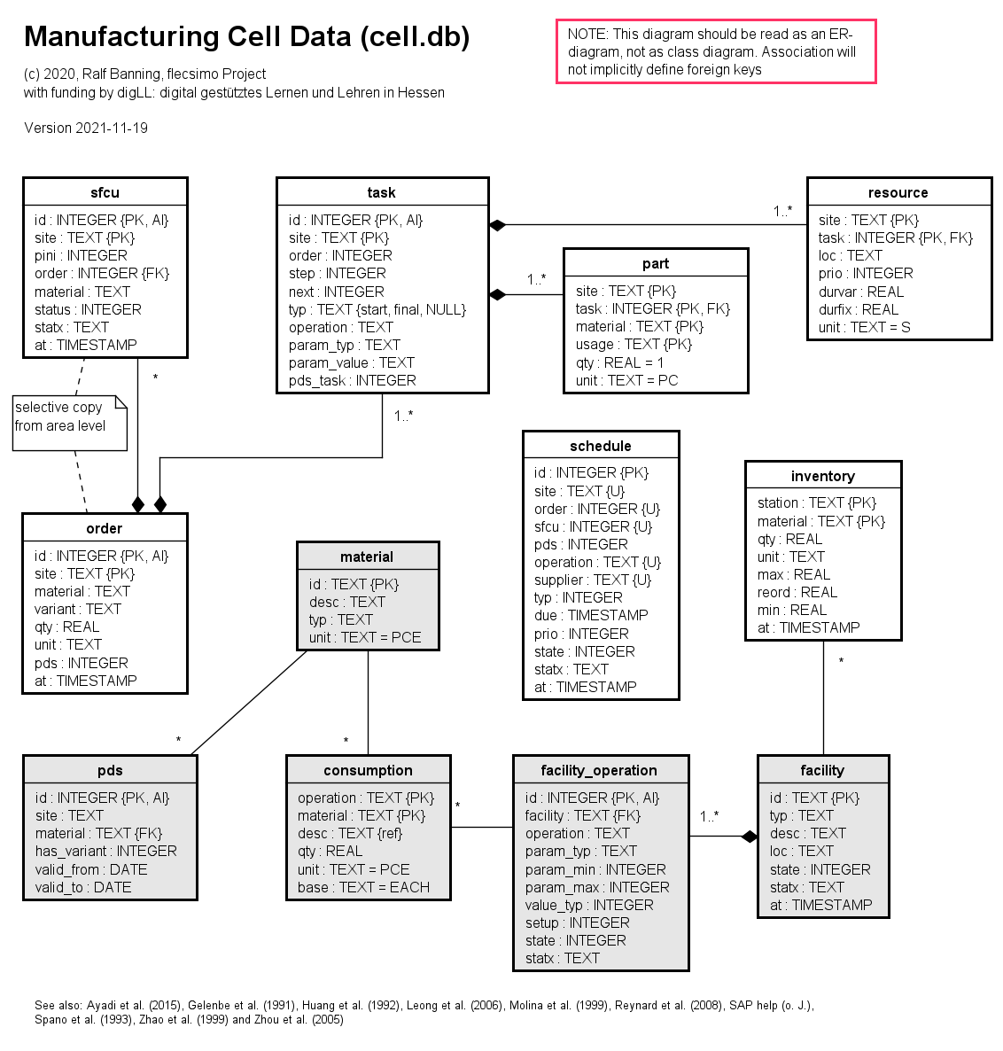
On cell level, which is also managing the station data, there is also some master data:
- The station entity contains a list of all stations in cell (normally just one!)
- The operation entity defines which operation a station (machine) provides, what is the specific setup time for this operation at this machine and so on.
- The consumption entity defines which production materials are consumed by an operation based on time or execution instance. Do not mix it up with material (parts) which will go into the product. Production material is also know as tertiary demand.
- The material entity on cell level is only used to store information on production materials
Obviously more entities will have to be defined with the project growing. The current model lacks esp. the following abilities:
- Map transportation units to sfcu (to identify inbound material at station level)
- Store transportation request, route or status
- Store Bill of Materials (BOM) data
- Store Warehouse information and transactions
Implementation
All entities shown on the diagrams above are instantiated by the following SQLite database tables:
- site.db on Factory or site level
- area.db on Shop or area level
- cell.db installed for each cell, sharing data between the cell and the station on cell
Cross level table design
Note: this documentation explains the de-factor implemented structure as provided with version 0.1.3. The model was simplified in a way that the differentiation between sfcu_task/oder_task, sfcu_part/order_part and sfcu_resource/order_resource was given up. As a reason may be mentioned, that this redesign reduces data duplication and simplifies the SQL-routines (which otherwise would do the same operations but in different table names). As a replacement for the destinction of oder data part and those used in sfcu context, a lookup from sfcu to order is used.
| Table | Description | Type1 | Data Flow | site | area | cell |
|---|---|---|---|---|---|---|
| consumption | Average consumption per material and operation, e. g. energy consumption or consumable materials. | |||||
| schedule | Matching of demand and supply. This is the origin (and target) for planning procedures on site level and request for quote (rfq) messages (currently only between area and cells). | T | site→area | |||
| facility | List of enrolled facilities, i. e. enrolled
Comprises a description and location of the facility. On cell level, this table acts as master data. | T / M | cell→area | |||
| facility_operation | Information on operations offered by a facility, e. g. parameterization and location of service. This does not imply, that an operation listed in this table is currently active. On site and area level this information will be updated dynamically during enrollment (or on update of these) whereas it remains statically defined on cell level (as master data). | T | cell→area | |||
| inventory | Current stock level of consumables for production. Also reorder quantities and minimum stock level are defined here. | |||||
| material | Material master data. This is used as a reference table for pds and to check if a new order may be accepted. | M |
| |||
| operation | Operation master data. Used as a reference table of pds. | M | ||||
| order | Header Record of an order. | T | site→area | |||
| order_parameter | Set of parameters for an order. Is used for roll out of pds structure during order planning. | T | ||||
| order_status | Status of an order. | T | ||||
| part | Parts list for an order task. Describes quantity and usage type of parts. | T | site→area | |||
| pds | Product Data Structure. Defines a "template" for order execution plans. | M | ||||
| pds_part | Template parts list. Describes quantity and usage type of parts. | M | ||||
| pds_resource | Template resource list. | M | ||||
| pds_task | Template task list. | M | ||||
| ref | External references for an order. Will be generated if an order is imported from an external third party or an ERP system. | T | ||||
| resource | Resource list for an order task. | T | site→area | |||
| task | Task list for an order. | T | site→area | |||
| sfcu | Shop Floor Control unit. | T | site→area |
1) Type M: Master Data, Type T: Transaction Data
Literature
Ayadi, M., Affonso, R. C., Cheutet, V. and Haddar, M. (2015) ‘Info Sim: Prototyping an information system for Digital Factory management’, Concurrent Engineering, vol. 23, no. 4, pp. 355–364.
Gelenbe, E. and Guennouni, H. (1991) ‘FLEXSIM: a flexible manufacturing system simulator’, European journal of operational research, vol. 53, no. 2, pp. 149–165.
Huang, H.-P. and Chang, P.-C. (1992) ‘Specification, modelling and control of a flexible manufacturing cell’, International Journal of Production Research, vol. 30, no. 11, pp. 2515–2543.
Kernler, H. (1995) PPS der 3. Generation: Grundlagen, Methoden, Anregungen, 3rd edn, Heidelberg, Hüthig.
Kurbel, K. (2013) Enterprise resource planning and supply chain management: Functions, business processes and software for manufacturing companies [Online], Dordrecht, Springer. Available at http://gbv.eblib.com/patron/FullRecord.aspx?p=1030480.
Leong, S., Lee, Y. T. and Riddick, F. (2006) ‘A core manufacturing simulation data information model for manufacturing applications’, Simulation Interoperability Workshop, Simulation Interoperability and Standards Organization, pp. 1–7.
Molina, A. and Bell, R. (1999) ‘A manufacturing model representation of a flexible manufacturing facility’, Proceedings of the Institution of Mechanical Engineers, Part B: Journal of Engineering Manufacture, vol. 213, no. 3, pp. 225–246.
Reynard, S., Gomis-Bellmunt, O., Sudrià-Andreu, A., Boix-Aragonès, O. and Benítez-Pina, I. (2008) ‘Flexible manufacturing cell SCADA system for educational purposes’, Computer Applications in Engineering Education, vol. 16, no. 1, pp. 21–30.
Spano, M. R., O’Grady, P. J. and Young, R. E. (1993) ‘The design of flexible manufacturing systems’, Computers in Industry, vol. 21, no. 2, pp. 185–198 [Online]. DOI: 10.1016/0166-3615(93)90135-N.
Zhao, J., Cheung, W. M. and Young, R.I.M. (1999) ‘A consistent manufacturing data model to support virtual enterprises’, International Journal of Agile Management Systems, vol. 1, no. 3, pp. 150–158.
Zhou, B.‐h., Wang, S.‐j. and Xi, L.‐f. (2005) ‘Data model design for manufacturing execution system’, Journal of Manufacturing Technology Management, vol. 16, no. 8, pp. 909–935.